Mercury Glide Path (GP)
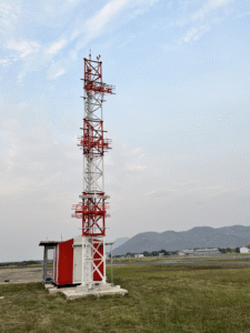
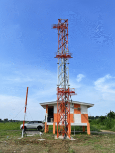
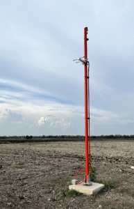
The Mercury Glide Path (GP) transmitter, developed by Airway Technologies, Inc., is an integral part of our Mercury ILS package, delivering precise vertical guidance signals to aircraft during final approach. While the Localizer provides horizontal alignment with the runway centerline, the GP ensures the aircraft maintains the optimal glideslope angle, enabling safe and accurate descent in all visibility conditions.
In designing the Mercury GP, we placed the needs of field engineers and airport operators at the forefront. Our engineering team conducted in-depth interviews with ILS maintenance professionals to identify real-world challenges and opportunities for innovation. As a result, the Mercury GP is engineered to minimize maintenance complexity and time on site, while enhancing fault resilience through robust quality control and factory pre-alignment.
To ensure dependable performance under extreme environmental conditions, the GP unit incorporates advanced temperature compensation circuits, allowing the system to maintain signal integrity and stability across a wide range of climates. This makes it an ideal solution for both high-traffic international airports and remote regional airfields.
Every Mercury GP unit shipped from our facility is CAT III–ready, enabling seamless future upgrades from CAT I to CAT II or CAT III operations without requiring hardware replacement. This forward-compatible design protects your investment and ensures long-term adaptability as airport needs evolve.
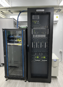
Critically, the Mercury Glide Path stabilizes its key transmission parameters immediately upon power-on, a major advantage for airports employing cold standby ILS configurations. This rapid stabilization capability significantly enhances operational reliability and readiness, even under time-sensitive or emergency conditions.
With the Mercury GP, Airway Technologies Inc delivers not only high-precision navigation signals, but also the confidence and efficiency that today’s air traffic infrastructure demands.


| System | Specification |
|---|---|
| Type | Dual Frequency (Fc ± 8 KHz) or Single Frequency |
| Frequency Range | 328.6 MHz to 335.4 MHz 150KHz spacing |
| Carrier Frequency Stability | ±0.0001%, 166Hz@332MHz |
| Operation Temperature | -10˚C to +55˚C |
| Relative Humidity | 0 ~ 90% |
| Primary Power | 110 V to 230V 47 to 63Hz |
| System and Standby Power | +24 V DC |
| Battery Backup | 4 hours or longer |
| Transmitter | Specification |
|---|---|
| CSB Output Power | Typically 5 Watt (+37 dBm) Adjustable 32dBm to 40dBm |
| CLR Output Power | Typically 0.5 Watt (+27 dBm) Adjustable 24dBm to 34dBm |
| CSB/SBO Power Stability | ±0.2dB |
| Harmonics / Spurious | 1uW / 10 uW |
| Total Harmonic Distortion | less than 1% |
| CSB/SBO Phase Adjustment | ±180 degree |
| Modulation | Frequency 90Hz±0.1%, 150Hz±0.1% Modulation Depth 80% (0%~90%) SDM Stability ±0.8% DDM Stability ±0.2% |
| Monitor | Specification |
|---|---|
| Input RF | Integral, Near Field |
| Input Level | – 10 ~ – 40 dBm |
| Monitor Stability | RF Power Value ±0.3dB DDM ±0.1% SDM ±1% |
| Alarm Limit | Programmable |